 |
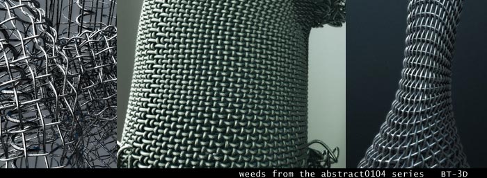
| In the following there are some tipps to build woven effects with the 'curves' function and displacement. You can surely build canvas also by hand or by using the macrosystem. This is just another way/idea to build them up. |
 |
| |
Setup the base:
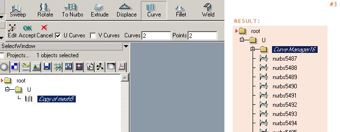
#1. Start with a nurbs rectangle with a density of 25 u and 25 v
#2. Drop it to a level and rename it to 'U'
#3. Go into the level ('U') and use the 'curve' function. Since U Curves is checked by default leave all as it is and simply click accept
|
 |
| |
#4. Now duplicate the whole level, select the curve manager in the new level and go to the property window. Uncheck the U curves and check the V curves checkbox instead.
|
 |
| |
#5. To get a good overview for the project you may want to change the name of the second level to 'V'
Now you have a U level containing the U curves and a V level containing the V curves and so the canvas building can begin.
The idea behind the following is really simple. We need to push up and down the points so that there a no intersection where the wire crosses. Since the curves manager allow us to displace the result of this function, we can setup a material to do what we want. In the following I use a custom channel to displace the generated curves but you can use the color channel for example also.
Setup the material:
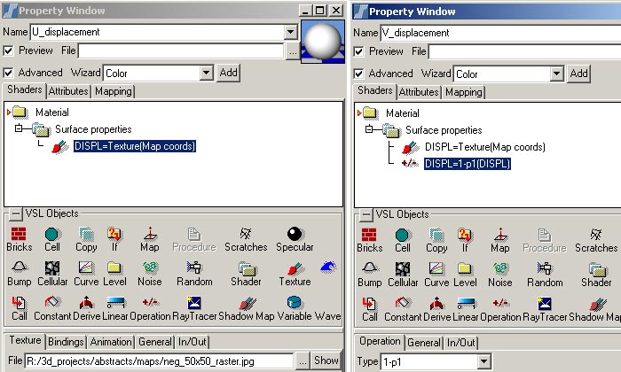
#6. create a new float channel and rename it to DISPL
#7. create a new VSL material and rename it to U_displacement
#8. check the advanced view and drop a surface shader into the material. Afterwards drop a texture handler inside.
#9. Now change the output of the texture to surface:DISPL |
 |
| |
The simple idea behind the material: We will use a black and white checker image where every black and white part represent one point of our mesh(curves). You can either paint your own (this should work without any drawing skills ;) or if you are lazy use the following image
#7. Since we want to push the V curves into the opposite direction, we simply duplicate the U_displacement material and rename it to V_displacement
#8. In the V_displacement material add an operation and change the input and output to surface:DISPL and finaly set the operation to 1-p1, which will invert the DISPL value
|
 |
| |
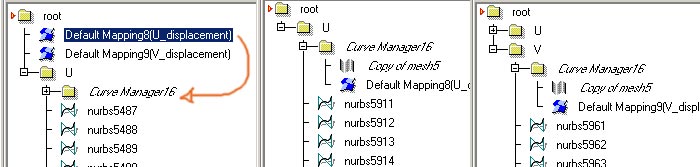
#9. Now the simplest way is to create two default material mappings (one for each material) into the root level, because if you try to create a default mapping to the mesh directly, RS will drop the mesh and the material into a new level and will sowhat duplicate the curves (no need for this)
#10. So, drop the U_diplacement material into the curve Manger level of the U level and the same for the V_displacement and the curve manager of the V level
|
 |
| |
#11. In the property window of the curves manager (of the U curves) change the channel to DISPL and set the displacement to for example 0,004 (this value depends on your mesh size and the diameter of the wires you will setup later) |
 |
| |
#12. Do the same for the curve manager of the V curves |
 |
| |
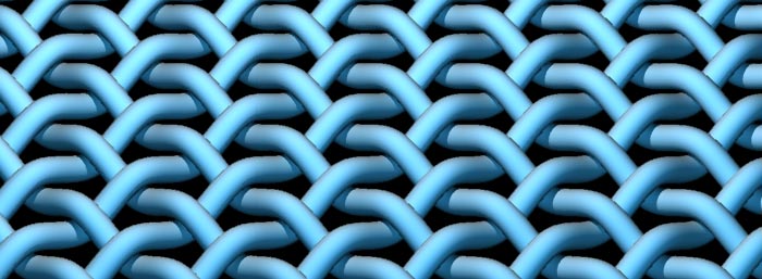
#13. Make a test render :)
|
 |
| |
#14. As I mentioned before the displacement value depends on the diameter you want to use for the wires. By change both you can create denser canvas
|
 |
| |
Finishing:
Here are some notes to enhance the canvas.
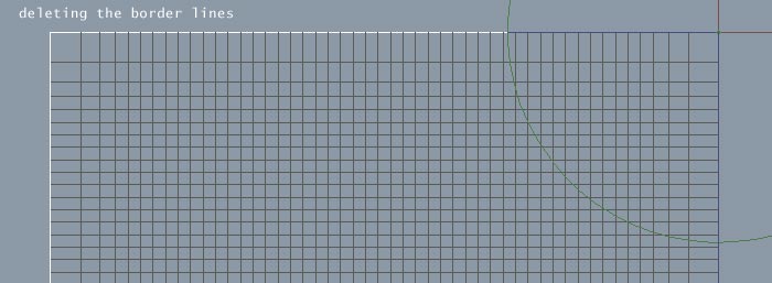
First you may have noticed that there are problems at the border of the canvas and second you will notice that if you make changes to the curve manager (for example the displacement value) the curves are generated new everytime, so changes you made to them (for example the diameter value) are lost.
To avoid this, I normaly freeze the canvas mesh by simply deleting the curve manager levels. You may want to keep a duplicate of the original generator levels to keep on playing. After deleting the curve manager levels you can modify the curves as you want. For example deleting the border curves, moving some points around, deform the mesh or changíng the diameter values and so on.
|


|
| |
Conclusion:
By using Nurbs meshes as input for the curves we are able to use the default mapping with the UV coords of the nurbs mesh. If your meshes are deformed you have maybe to modify your UV spaces carefully to get useful displacement results.
Changing the values of the generated curves, for example create more curves from a mesh, leads to the need for a denser image according to the number of nurbs curves.
I'm currently working on a procedural material to displace the mesh without the need of images, but it's not ready to publish at the moment.
|
 |
|
| top |
| ©2005 BT-3D . [Tim Borgmann] . www.bt-3d.de |