| This is some basic stuff to explain how nurbs curves work. |
 |
| |
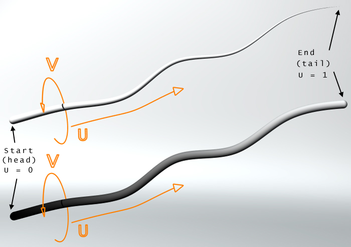
First of all it's important to realize that nurbs curves have an UV space. Otherwise the following materials and ideas won't work at all. The U value ranges from 0 to 1 along length from start to end point. So the U value is the important one for changing the appearance along the curve's length. (See image above)
By using this U value in a material you have the possibility to create a lot of effects.
A simple use is for example to change the radius of the curve along it's length. To do this, perform the following steps:
- create a nurbs curve, open properties at the Gen tab and clear the 'Invisible in photo realistic rendering' checkbox
- create a custom float channel called 'MYRADIUS'
- create a new VSL material and switch to advanced mode
- drop a shader object into the VSL window and change it to 'scanline'
- drop a curve object into the scanline shader and change the output value to 'scanline:MYRADIUS'
- change the input (which should be Scanline : Map coords) from 'all sub channels' to 'x' since we want the U value as input
- now the curve runs from x.0,y.0 to x.1,y.1 which means that the radius (the y value) will be 0 at the start and 1 at the end of our nurbs curve. So by changing the two curve points to x.0, y.1 and x.1,y.0 we will get the same result as if we had set the head and tail radius in the nurbs curve property window to 1 and 0. The result will be a nurbs curve that gets thinner at it's end point.
- so far so good. By using the VSL curve to control the radius we are able to create much more shapes than a simple linear falloff. Just change the curve a little bit to make it all look more interesting.
- since the output value of the curve ranges from y.0 to y.1 and we will use this value for our nurbs curve displacement, we have to convert this value to useful mm values. This is very important when using displacement in RS, because displacement is measured in real space values (1 = 1 meter).
- simply drop a linear object below the curve object and change input and output to 'scanline:MYRADIUS'
- now set multiply value to for example 0,001 ( equal to 1 mm).
- go to the nurbs curve property window (Spec tab) and change the 'max displacement (mm)' value to 1 and set 'Radius channel' to our custom MYRADIUS channel
- It's very important to realize that the value of 'max displacement' and the value of the multiply part of the linear VSL object are related and aligned
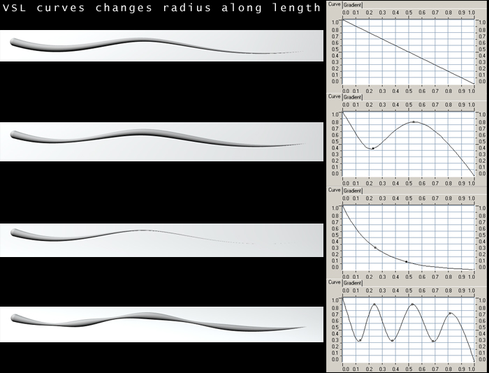
- take a look at the images below to see how VSL curves can modify the shape of the nurbs curve
HINTS:
- It's often useful to decrease the quality of the nurbscurve. You can use the quality slider in the property window (Spec tab) or use the new 'geometry quality = low' function in the Rendersettings properties Misc tab. In many cases low values are still suitable and speed up rendering. On the other hand, since such curves are usualy thin, it's useful to set the 'output scale' in the postimage property window scaling tab to 0,5 (aka supersampling). In animations a suitable amount of motionblur is very helpful to avoid flickering effects.
- If you want to change the radius of the curve (displacement) it's advisable to use a custom float channel. It's easier to handle than an existing channel like 'color'.
- By using for example boolean VSL curves it's possible to cut off parts of the nurbs curve (y=0 = radius=0). When animating such a curve it can look like a growing process. (see nurbscurve animation)
- If you create a nurbs curve from several single curves with the ´Concatenate´ function it's useful to set the 'parametrization' to 'uniform' in the properties window to ensure an evenly distributed UV space along the curve.
|
 |
|